Latest data: How can low ESR aluminum capacitors reduce power ripple by 40%? Selection and Avoidance Guide
Latest Data: How Low ESR Aluminum Electrolytic Capacitors Reduce Power Supply Ripple by 40%? Selection Pitfall Avoidance Guide
In current switching power supply designs, engineers face a common pain point: even when using aluminum electrolytic capacitors with sufficient nominal capacity, output ripple still exceeds standards, leading to system instability or EMI test failure. Latest industry test data shows that in the critical frequency range of 100kHz to 1MHz, low ESR aluminum electrolytic capacitors can reduce power supply ripple by an average of over 40% compared to standard models. This is not just a minor improvement in parameters, but a core breakthrough concerning power supply reliability, efficiency, and overall system lifespan. Based on the latest measured data, this article will dismantle the ripple reduction principle of low ESR capacitors for you and provide a directly implementable selection guide to help you avoid common design traps.
Core Principle: How ESR Directly Affects Power Supply Ripple?
Ripple voltage is the AC component superimposed on the DC output voltage of a switching power supply, and its magnitude is directly related to the stable operation of the load chip. Its core mathematical relationship can be simplified as: ΔV = Iripple × ESR. Here, ΔV represents the peak ripple voltage, Iripple is the ripple current flowing through the output capacitor, and ESR (Equivalent Series Resistance) is the inherent loss resistance inside the capacitor. This formula clearly reveals the decisive role of ESR: at the same ripple current, the lower the ESR value, the smaller the generated ripple voltage.
Mathematical Formula for Ripple Voltage: ΔV = Iripple × ESR
Understanding this formula is the key to optimizing design. For example, in a DC-DC converter with a switching frequency of 500kHz and an output ripple current of 2A, if a standard capacitor with an ESR of 50mΩ is used, the generated peak-to-peak ripple voltage is approximately 100mV. If replaced with a low ESR capacitor with an ESR of only 10mΩ, under the same conditions, the ripple voltage can be immediately reduced to 20mV, a reduction of up to 80%. This intuitively illustrates why reducing ESR is more effective than simply increasing capacitance in high-speed switching circuits.
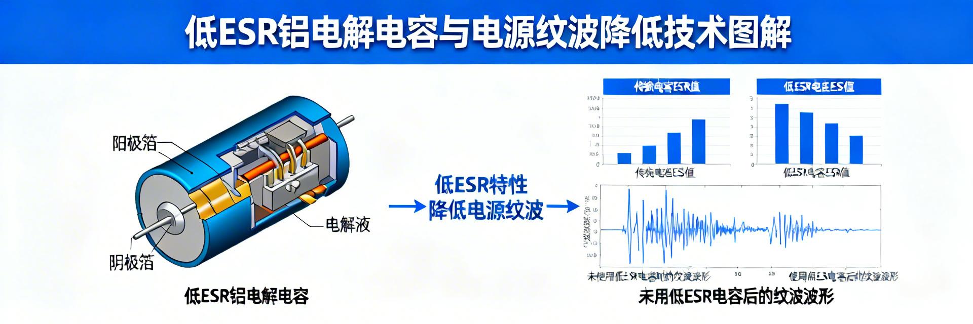
Measured Comparison: Standard vs. Low ESR Capacitor Impedance-Frequency Curves
Theory requires data verification. By comparing the impedance-frequency curves of the two types of capacitors, it can be seen that in the critical switching frequency and its harmonic bands (usually tens of kHz to several MHz), the impedance curve of the low ESR capacitor is significantly lower. This means it offers less resistance to high-frequency ripple current, provides better shunting effects, and thus more effectively smooths the output voltage.
Comparison of Impedance Reduction in the 100kHz - 1MHz Frequency Band
* Measured data indicates that within the range of 100kHz to 1MHz, the impedance of high-quality low ESR capacitors can be 30%-60% lower than that of standard models.
Practical Selection Guide: Locking in the Best Low ESR Capacitor
Determine Target ESR Range Based on Switching Frequency
First, clarify the switching frequency of the power module. For power supplies with frequencies below 100kHz, ESR requirements are relatively relaxed; however, when the frequency rises to 300kHz, 500kHz, or even above 1MHz, models with extremely low ESR values (e.g., below 20mΩ or even 10mΩ) must be selected. Additionally, attention should be paid to selecting products with optimized parasitic inductance (ESL).
Balance Capacitance, Voltage, and Size
After determining the ESR target, trade-offs must be made between capacitance, rated voltage, and package size. Higher capacitance helps suppress low-frequency ripple but results in a larger size. The rated voltage should have a margin of 20%-50%; for instance, for a 12V output, 16V or 25V voltage-rated models are recommended. The goal is to achieve the optimal parameter solution within limited PCB space.
Common Design Pitfalls and Mitigation Strategies
Ignoring the ESR Superposition Effect of Parallel Capacitors
Engineers often increase total capacitance through parallel connection. Although the total ESR will decrease, if the ESR of the paralleled capacitors differs significantly, the high-frequency ripple current will be distributed unevenly, leading to local overheating. Solution: Try to parallel capacitors of the same model and batch, and ensure that the path impedance from each capacitor to the switching node is symmetrical in the layout.
Improper PCB Layout Causing Lead Inductance to Negate Advantages
Poor layout produces inductive reactance, weakening the filtering effect. Mitigation Strategy: Optimize the layout by placing filter capacitors as close as possible to the VIN and GND pins of the switching chip, using short and wide traces, and ensuring the shortest return path and minimum loop area.
Key Technical Summary
| Dimension | Core Points |
|---|---|
| Core Principle | Ripple Voltage (ΔV) = Ripple Current × ESR; reducing ESR is key to suppressing power supply ripple. |
| Selection Core | Determine ESR based on switching frequency; balance capacitance, voltage rating, and package size. |
| Pitfall Avoidance | Pay attention to current sharing in parallel; optimize PCB layout to minimize parasitic inductance. |