Latest Data Report: How Low ESR and High Ripple Current Can Increase Capacitor Life by 300%?
In today's pursuit of extreme energy efficiency and reliability in electronic design, engineers face a critical challenge: how to make core filter capacitors "survive" longer under harsh operating conditions? Latest industry test data shows that by synergistically optimizing low ESR and high ripple current tolerance, the predicted lifespan of some advanced aluminum electrolytic capacitors has achieved a leap of up to 300%. This is not just an improvement in parameters, but a profound reconstruction of the physical mechanism of capacitor failure. This article will deeply analyze the data, principles, and selection guidelines behind this "lifespan miracle," helping you achieve reliability breakthroughs at the system level.
Data Visualization of Lifespan Improvement Comparison
* Based on accelerated test simulation data under the same temperature rise conditions
Lifespan Killers: The Synergistic Destruction Mechanism of ESR and Ripple Current
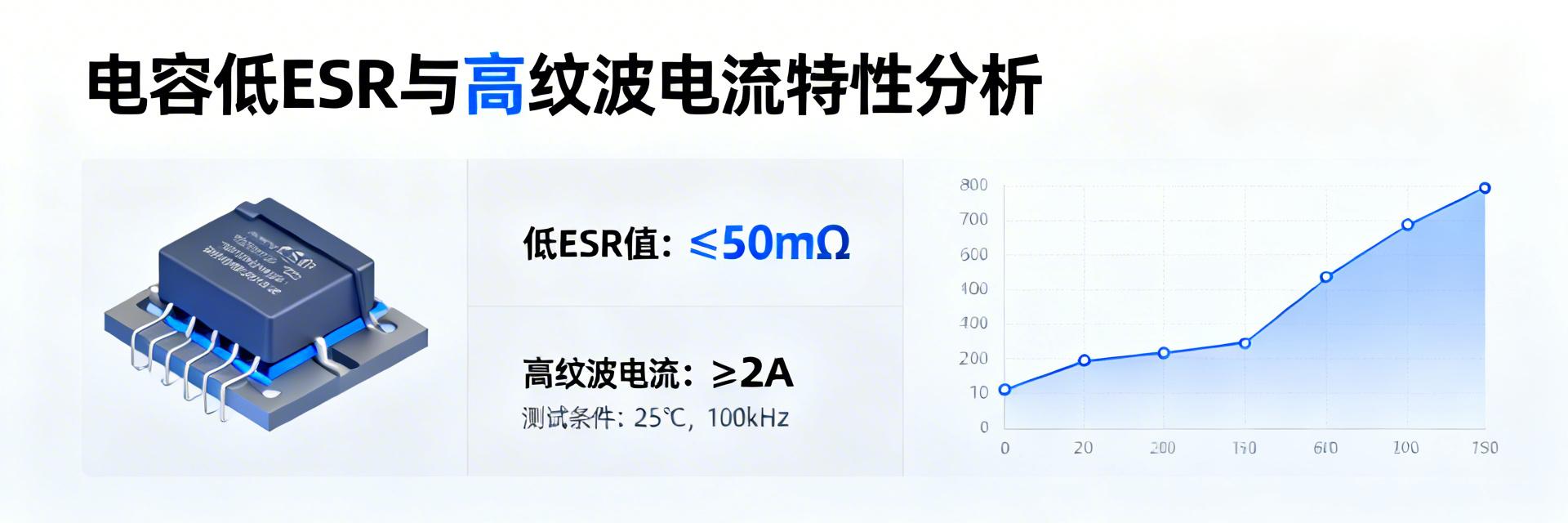
Capacitor lifespan degradation is not caused by a single factor, but is dominated by the thermal and chemical effects under the joint action of Equivalent Series Resistance (ESR) and ripple current. Understanding this synergistic destruction mechanism is the first step in effective lifespan optimization.
Thermal Failure Model: The Harsh Reality of the P = I² × ESR Formula
The power loss generated inside the capacitor due to ripple current strictly follows the formula P = IRMS² × ESR. Power loss directly converts into heat, causing the temperature of the capacitor element to rise. For electrolytic capacitors, the evaporation rate of the internal electrolyte has an exponential relationship with temperature; for every 10°C rise in temperature, the lifespan is approximately halved. High ESR values can drastically shorten lifespan even at moderate currents.
The "Fatigue Effect" of Ripple Current
High-frequency alternating current causes repeated stress changes in the microstructure of the oxide film, similar to the "fatigue effect" in metals, which may lead to local defects. Meanwhile, the back-and-forth migration of ions accelerates electrolyte aging. When ESR is high, the temperature rise exacerbates these electrochemical aging processes, forming a vicious cycle of "thermal-electrical" dual accelerated failure.
Data Deep Dive: Key Technical Paths for 300% Lifespan Improvement
Achieving a multi-fold increase in capacitor lifespan relies on synergistic innovation in materials science and structural engineering. The latest technical paths mainly revolve around reducing ESR and enhancing ripple current tolerance.
Material Innovation: Application of High-Conductivity Polymers
Using ultra-high purity aluminum foil and optimizing etching processes increases the effective surface area. The application of hybrid polymer electrolytes, compared to traditional liquid electrolytes, offers lower ionic migration impedance and better high-temperature stability, significantly reducing high-frequency ESR.
Structural Optimization: Etching Processes and Connection Technologies
Through fine and uniform etching pit structures, the electrolyte contacts the aluminum foil more fully, reducing contact resistance. Improving winding techniques and internal connections reduces the impedance of current collection paths and avoids the generation of local hot spots.
Practical Selection Guide: How to Quantitatively Evaluate Capacitor Lifespan?
The key lies in understanding the correlation between core parameters and matching them with your specific application scenario.
Scenario Matching Recommendation Table
| Application Scenario | Core Challenges | Selection Focus |
|---|---|---|
| Switching Power Supply (SMPS) | High frequency, large ripple current | Ultra-low ESR at switching frequency, high rated ripple current |
| Automotive Electronics | Extreme high temperature, high vibration | 125°C+ lifespan rating, mechanically stable structure |
| Industrial Drives | Drastic load changes, low-frequency ripple | Broadband low ESR, high Root Mean Square (RMS) current tolerance |
Selection Tip: Lifespan estimation is based on the formula L = L₀ × 2(T₀-Tₐ)/10 × (I₀/Iₐ)ⁿ. Reducing operating temperature and ripple current has an exponential positive impact on lifespan.
Test Verification: The Reliability Leap from Datasheets to Real Operating Conditions
Accelerated Life Testing (ALT) Data Interpretation
Testing is conducted by applying stresses much higher than rated values (e.g., 125°C, 2x ripple current). When interpreting, focusing on the growth rate of ESR is more critical than focusing on capacitance decay, as an increase in ESR is often a precursor to failure.
Multi-frequency Loss Calculation
In real circuits, multi-frequency ripples exist. A capacitor with extremely low ESR at 100kHz might heat up significantly at 120Hz. Multi-frequency point superposition calculations must be performed, and reasonable temperature derating estimations should be made based on the calculated element temperature rise.
Key Summary
- ✓ Synergistic Optimization is Key: Low ESR reduces heat generation, while high ripple current capability ensures structural stability; together they resist dual thermal-electrochemical aging.
- ✓ Dual-Wheel Drive of Materials and Structure: The 300% leap in lifespan relies on the synchronized innovation of high-conductivity polymer electrolytes and high-rate etched aluminum foil.
- ✓ Data-Driven Verification: Quantitative lifespan estimation must be combined with ESR frequency curves and current spectrums, using ALT to bridge the gap between datasheets and the real world.